Y should be true if the number is prime.
Design a combinational circuit with three inputs and three outputs.
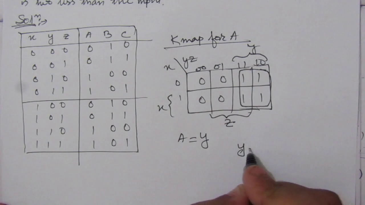
Design a combinational circuit with three inputs x y and z and three outputs a b and c.
The half adder circuit is designed to add two single bit binary number a and b.
Specifically x should be true if the number is divisible by 3.
Half adder is a combinational logic circuit with two inputs and two outputs.
Eg 2 10 3 10 5 10 7 10.
When the binary input formed from xyz is 0 1 2 or 3 the binary output produced by abc is.
When the binary input is 0 1 2 or 3 the binary out.
When the binary input is 0 1 2 or 3 the binary output is 1 greater than the input.
When the binary input is 4 5 6 or 7 the binary output is three less than the input.
Compare two 1 bit numbers.
When the binary input is 4 5 6 or 7 the binary output is one less than the input.
Given two input bits a and b produce three outputs x y and z so that x is 1 only when only when a b y is 1 only when a b and z is 1 only when a b learn more.
When the binary input is 0 1 2 or 3 the binary output is one greater than the input.
When the binary input is 0 1 2 or 3 the binary output is one greater than the input.
Design a combinational circuit with 4 inputs a3 a2 a1 a0.
Design a combinational circuit with three inputs x y and z and three outputs a b and c.
We re going to elaborate few important combinational circuits as follows.
And z should be true if the number is a.
Follow the above listed points to design the logic diagram as per the given statement.
Design a combinational circuit with three inputs x y and z and the three outputs a b and c.
Design a combinational circuit with three inputs x y and z and three outputs a b and c.
When the binary input is 4 5 6 or 7 the binary output is one less than the input.
Example of combinational logic circuit.
Design a combinational circuit with three inputs x y z and three outputs a b and c.
A combinational circuit can have an n number of inputs and m number of outputs.
When the binary input is 4 5 6 or 7 the binary output is one less than the input.
4 5 design a combinational circuit with three inputs x y and z and three outputs a b and c.
When the binary input is 0 1 2 or 3 the binary output is two greater than the input.
The inputs represent a binary number in the range 0 15 and the outputs represent characteristics of the numbers.